 English
Views: 13 Author: Site Editor Publish Time: 2025-11-05 Origin: Site
Struggling with overheating components in your electronic device without active cooling? Finding the right passive heat sink is crucial for reliability and performance, but the "best" solution isn't one-size-fits-all. This guide will help you determine if a better passive heat sink exists for your specific application by analyzing your thermal needs, exploring advanced designs, and comparing materials to ensure optimal, fan-less heat dissipation.
You've got a component running hot, and adding a fan just isn't an option. Maybe it's a noise-sensitive medical device, a dust-prone industrial control, or a compact, sealed outdoor enclosure. Passive cooling is your only path, but the generic finned block you're using just isn't cutting it. You're left wondering: Is there a better passive heat sink for my application? The answer is almost certainly yes, but finding it requires a deeper dive than simply grabbing the largest one you can fit. This article will guide you through a systematic approach to identify and select a superior passive heat sink tailored to your unique thermal challenges, ensuring your device stays cool, quiet, and reliable.
Before seeking a "better" passive heat sink, you must precisely define your current thermal problem.
To determine if a better passive heat sink exists for your application, you must first accurately quantify your component's heat dissipation (TDP), identify its maximum allowable operating temperature, and thoroughly characterize the ambient conditions and available space. Understanding these specific thermal and environmental constraints is foundational, as it dictates the required thermal resistance and ultimately guides the selection of an optimized passive heat sink solution, moving beyond generic assumptions.
A vague understanding leads to generic solutions. Let's get specific.
Component Thermal Design Power (TDP): This is the total heat (in Watts) your component generates under its worst-case operating conditions. Don't rely on typical values; find the maximum specified by the manufacturer.
Example: A CPU might have a 65W TDP. A power LED array could be 30W.
Practical Impact: This directly determines how much heat your passive heat sink must dissipate.
Maximum Junction Temperature (Tj_max): The highest temperature the semiconductor junction can safely reach. Exceeding this drastically reduces lifespan.
Example: Many semiconductors have a Tj_max of 125°C or 150°C.
Practical Impact: This sets the upper limit for your thermal design.
Desired Operating Temperature (Tj_desired): Often, you'll aim for a junction temperature significantly below Tj_max to ensure long-term reliability and performance stability.
Example: Aiming for 85°C for a component with a 125°C Tj_max.
Practical Impact: This directly influences the required thermal resistance of your heat sink.
Ambient Temperature (Ta): The temperature of the air surrounding the heat sink. This is critical for passive cooling, as it's the ultimate heat sink.
Example: An outdoor enclosure might see Ta up to 50°C. An indoor server room might be 25°C.
Practical Impact: A higher Ta means less temperature difference for heat transfer, requiring a more efficient heat sink.
Airflow Conditions: For passive heat sinks, this means natural convection. Are there any obstructions? Is the heat sink oriented correctly for natural airflow?
Example: A heat sink with vertical fins allows for better natural convection than horizontal fins.
Practical Impact: Poor airflow significantly degrades passive heat sink performance.
Available Space (Volume/Footprint): The physical dimensions you have for the heat sink. This is often the most restrictive constraint.
Example: A compact medical device might only allow a 50x50x20mm heat sink.
Practical Impact: Limits the size and type of heat sink you can use, pushing towards more advanced designs or materials.
Mounting Orientation: How the heat sink will be mounted (e.g., fins vertical, horizontal).
Example: Vertical fins are generally superior for natural convection.
Practical Impact: Influences fin design and overall heat sink effectiveness.
With these values, you can calculate the maximum allowable thermal resistance for your heat sink:
R_sa (Heat Sink to Ambient) = (Tj_desired - Ta) / TDP - R_jc (Junction to Case) - R_cs (Case to Heat Sink)
R_jc: Provided by the component manufacturer.
R_cs: Thermal resistance of the Thermal Interface Material (TIM).
Practical Impact: This calculated R_sa is your target. A "better" passive heat sink will have a lower R_sa than your current solution, or achieve the same R_sa within tighter constraints. KingKa Tech's thermal engineers can assist in these calculations and simulations.
Once your thermal requirements are clear, the next step is to explore how design choices can significantly enhance passive heat sink performance.
Optimizing passive heat sink design involves maximizing surface area for natural convection while minimizing airflow resistance and thermal spreading resistance within the heat sink base. Key design considerations include fin geometry (tall, thin, widely spaced fins are often best), base thickness for efficient heat spreading, and overall heat sink orientation. Generic designs often underperform because they fail to balance these critical factors for specific passive cooling environments.
Passive heat sinks rely entirely on natural convection and radiation, making design paramount.
Fin Height: Taller fins increase surface area, improving heat transfer. However, there's a point of diminishing returns where the boundary layer from adjacent fins merges, hindering airflow.
Example: For natural convection, fins that are too short won't generate enough buoyancy-driven flow.
Practical Impact: Taller fins are generally better for passive cooling, within practical limits.
Fin Thickness: Thinner fins reduce material usage and weight, but must be thick enough to conduct heat efficiently from the base to the fin tip.
Example: Very thin fins might have a poor fin efficiency, meaning the tip is much cooler than the base.
Practical Impact: A balance is needed to ensure heat reaches the entire fin surface.
Fin Spacing: This is critical for passive cooling. Fins that are too close together restrict natural airflow, creating a "chimney effect" that chokes convection. Wider spacing allows for better air movement.
Example: For forced convection, fins are typically much closer. For passive, they need to be wider apart.
Practical Impact: Optimal fin spacing is crucial for maximizing natural convection.
Fin Type:
Extruded Fins: Cost-effective for aluminum, but limited aspect ratios.
Skived Fins: Can create very thin, high-density fins from a single block, eliminating interface resistance.
Bonded Fins: Allows for very tall, thin fins with wider spacing, often combining a copper base with aluminum fins. KingKa Tech specializes in these.
Pin Fins: Offer omnidirectional airflow but generally less effective than plate fins for natural convection due to lower surface area per volume and higher flow resistance.
Base Thickness: A sufficiently thick base is essential to spread heat efficiently from the concentrated heat source across the entire heat sink, ensuring all fins are utilized.
Example: A thin base on a large heat sink will result in hot spots directly above the component, with cooler, underutilized fins further away.
Practical Impact: A thicker base reduces spreading resistance, improving overall heat sink effectiveness.
Material Choice for Base: As discussed in previous articles, copper is superior for heat spreading due to its high thermal conductivity.
Example: A copper base with aluminum fins (a mixed composition heat sink) leverages copper's spreading power with aluminum's lightweight fins.
Practical Impact: Critical for high-power density components.
Vertical Fins: For natural convection, fins should ideally be oriented vertically to allow hot air to rise unimpeded, creating a natural chimney effect.
Example: A heat sink mounted horizontally with fins parallel to the ground will perform significantly worse.
Practical Impact: Design the enclosure and mounting to facilitate vertical fin orientation whenever possible.
KingKa Tech's Expertise: Our design team uses advanced thermal analysis software to simulate natural convection and optimize fin geometry, spacing, and base thickness for your specific passive cooling application, ensuring maximum performance within your physical constraints.
While design is crucial, the choice of heat sink material can provide a significant performance boost for passive cooling.
For enhanced passive heat sinks, advanced materials offer superior thermal conductivity, lower density, or unique anisotropic properties compared to standard aluminum. Copper excels in heat spreading for high-power density components, while pyrolytic graphite sheets (PGS) provide ultra-lightweight, directional heat spreading. Mixed compositions, such as copper-aluminum bonded fins or vapor chambers, are particularly effective, leveraging the strengths of multiple materials to achieve higher thermal performance within passive cooling constraints.
Beyond standard aluminum, these materials offer distinct advantages:
Thermal Conductivity: Approximately 380-400 W/(m·K), nearly double that of aluminum.
Advantages for Passive:
Superior Heat Spreading: Rapidly moves heat from the component across the heat sink base, ensuring all fins are effectively utilized. This is critical for passive designs where a large surface area is needed.
Higher Fin Efficiency: Due to higher conductivity, copper fins can be more effective at transferring heat to their tips, even if they are relatively long.
Disadvantages: High density (heavy) and higher cost.
Practical Application: Ideal for high-power density components where weight is less critical, or as a base material in a mixed-composition heat sink.
Thermal Conductivity: Extremely high in-plane (700-1700 W/(m·K)), but very low through-plane.
Advantages for Passive:
Ultra-Lightweight: Significantly lighter than aluminum or copper.
Exceptional Heat Spreading (Planar): Can rapidly spread heat across a large surface area, effectively turning a small hot spot into a larger, cooler area for a traditional heat sink to dissipate from.
Disadvantages: Anisotropic nature requires careful design, brittle, high cost, poor through-plane conductivity means it's usually a spreader, not a primary fin material.
Practical Application: Often used as an intermediate layer between a hot component and a conventional aluminum heat sink, or to spread heat within very thin devices (e.g., smartphones) to a larger enclosure surface.
Copper Base with Aluminum Fins:
Concept: Combines copper's excellent heat spreading at the base with aluminum's lightweight and cost-effective fins.
Advantages for Passive: Maximizes heat spreading from the source while keeping the overall heat sink weight and cost lower than an all-copper solution. Allows for taller, wider-spaced aluminum fins for better natural convection.
Practical Application: High-performance passive CPU coolers, power electronics. KingKa Tech excels in manufacturing these bonded fin heat sinks.
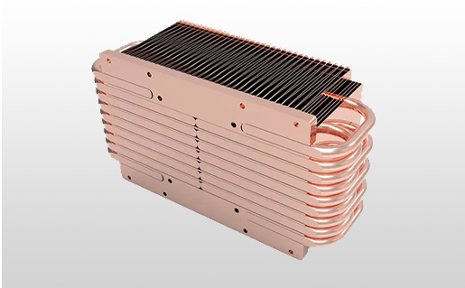
Vapor Chambers/Heat Pipes with Aluminum Fins:
Concept: Vapor chambers (flat heat pipes) or individual heat pipes are integrated into an aluminum fin stack. They use a two-phase fluid to transfer heat with extremely high effective thermal conductivity (thousands of W/(m·K)).
Advantages for Passive: Extremely efficient at moving heat from a concentrated hot spot to a larger, remote fin array, overcoming spreading resistance limitations of solid metals. This allows for larger, more effective passive heat sinks.
Practical Application: High-power passive GPU coolers, industrial PCs, sealed enclosures where heat needs to be moved from a component to the enclosure wall.
KingKa Tech's Expertise: We offer a range of advanced material solutions, including precision-machined copper cold plates, bonded fin heat sinks (copper base/aluminum fins), and integration of heat pipes/vapor chambers, all optimized for your passive cooling needs.
Beyond the core heat sink design and material, optimizing the surface and interfaces is crucial for passive cooling efficiency.
For passive heat sinks, surface treatment and thermal interface materials (TIMs) play a critical role in minimizing thermal resistance. Anodizing or black nickel plating enhances emissivity, improving radiative heat transfer, while selecting the correct TIM (e.g., thermal grease, gap pads, phase change materials) is essential to reduce contact resistance between the component and the heat sink. Neglecting these interface optimizations can significantly degrade overall passive cooling performance, even with an otherwise well-designed heat sink.
Every layer of resistance adds up, especially in passive systems.
Emissivity: The ability of a surface to emit thermal radiation. A perfectly black body has an emissivity of 1.0. Bare aluminum has a low emissivity (around 0.05-0.1).
Anodizing (Black): A common surface treatment for aluminum heat sinks. It creates a porous oxide layer that can be dyed black.
Advantages: Increases emissivity significantly (to 0.8-0.9), enhancing radiative heat transfer. Also provides corrosion resistance and electrical insulation.
Disadvantages: Adds a small thermal resistance layer, but the benefit from increased radiation usually outweighs this for passive cooling.
Black Nickel Plating: Can be applied to copper heat sinks.
Advantages: Increases emissivity for copper, provides corrosion protection.
Disadvantages: Adds cost and a thin thermal resistance layer.
Practical Impact: For passive heat sinks, radiation can account for 20-40% of the total heat dissipation, especially at higher temperatures. Enhancing emissivity is a low-cost way to boost performance.
Purpose: To fill microscopic air gaps between the component's surface and the heat sink's base, which are poor thermal conductors.
Types of TIMs:
Thermal Grease/Paste: High performance, low thermal resistance, but can pump out over time and is messy.
Thermal Gap Pads: Easier to apply, accommodate larger gaps, but generally higher thermal resistance than grease.
Phase Change Materials (PCMs): Solid at room temperature, melt at operating temperature to fill gaps, offering good performance and easier application than grease.
Metallic TIMs (e.g., Indium foil): Very low thermal resistance, but expensive and require high clamping force.
Adhesive Tapes: Convenient for light components, but higher thermal resistance.
Key Considerations:
Thermal Conductivity: Higher is better (W/(m·K)).
Bond Line Thickness (BLT): Thinner is better.
Compressibility/Conformability: Ability to fill gaps effectively.
Operating Temperature Range: Must be stable over the expected temperature range.
Reliability: Long-term stability, resistance to pump-out or drying.
Practical Impact: A poor TIM can add significant thermal resistance (R_cs), negating the benefits of an optimized heat sink. Selecting the right TIM and ensuring proper application (e.g., correct clamping force) is critical.
KingKa Tech's Expertise: We can advise on optimal surface treatments and recommend suitable TIMs based on your application's specific requirements, ensuring every aspect of your passive thermal path is optimized.
Sometimes, a purely solid heat sink isn't enough, even with optimization. This is where hybrid passive solutions come into play.
When conventional solid passive heat sinks reach their limits, hybrid passive solutions, primarily incorporating heat pipes or vapor chambers, offer significantly enhanced thermal performance. These two-phase devices effectively transform a concentrated heat source into a larger, more uniform heat sink surface, drastically reducing spreading resistance and enabling more efficient heat dissipation through natural convection or radiation. They are ideal for high-power density components in space-constrained or sealed passive cooling environments.
Hybrid passive solutions leverage the power of phase change to move heat more efficiently.
How they work: A sealed tube containing a working fluid (e.g., water, ammonia) and a wick structure. Heat at one end (evaporator) vaporizes the fluid, which travels to the cooler end (condenser), condenses, and returns via the wick.
Effective Thermal Conductivity: Thousands of W/(m·K), far exceeding solid metals.
Advantages for Passive:
Overcome Spreading Resistance: Can move heat from a small hot spot to a much larger, remote fin array with minimal temperature drop.
Flexibility: Can be bent to navigate around components and distribute heat to optimal dissipation areas.
Passive Operation: Requires no external power.
Disadvantages: Performance is gravity-dependent (wicking limits against gravity), limited power handling per pipe, can be sensitive to orientation.
Practical Application: Often embedded in the base of an aluminum fin stack to spread heat from a CPU/GPU to the entire fin array, or to transfer heat from an internal component to an external enclosure wall.
How they work: Similar to heat pipes but in a flat, planar form. They spread heat across a 2D surface.
Effective Thermal Conductivity: Also thousands of W/(m·K) in the spreading plane.
Advantages for Passive:
Superior Planar Spreading: Excellent for taking heat from a small area and spreading it uniformly over a large base, which then feeds into a fin stack.
Lower Profile: Can be thinner than multiple heat pipes.
Passive Operation: Requires no external power.
Disadvantages: More complex and expensive to manufacture than heat pipes, limited to planar spreading.
Practical Application: High-performance passive CPU/GPU coolers, power modules, where a large, uniform heat sink base is required to feed into a fin array.
How they work: A two-phase device similar to a heat pipe but without a wick structure. Relies entirely on gravity for condensate return.
Advantages for Passive: Can handle very high heat loads, simpler construction than heat pipes.
Disadvantages: Strictly gravity-dependent (evaporator must be below condenser), larger form factor.
Practical Application: Large-scale passive cooling systems, such as for telecom cabinets or industrial equipment where vertical orientation is guaranteed.
KingKa Tech's Expertise: We design and integrate heat pipes and vapor chambers into custom passive heat sink solutions, providing significantly enhanced thermal performance for your most demanding passive cooling applications. Our liquid cold plate expertise also extends to advanced two-phase systems.
Once you've designed or selected a potentially "better" passive heat sink, rigorous evaluation is essential.
Evaluating passive heat sink performance requires precise measurement of component junction temperature under realistic operating conditions, calculating the actual thermal resistance, and comparing it against the target. This involves using thermocouples, thermal cameras, and controlled environmental chambers to simulate real-world ambient temperatures and airflow. Without empirical testing, theoretical optimizations remain unverified, risking thermal failure in the field and undermining the goal of finding a truly better passive solution.
Don't just assume your new design is better; prove it.
Thermocouples: Small, accurate temperature sensors.
Placement: Attach directly to the component case (Tc), heat sink base, and various fin locations. Crucially, measure ambient temperature (Ta) away from the heat sink's influence.
Practical Impact: Provides precise point temperature data.
Thermal Imaging Camera: Non-contact, visual representation of surface temperatures.
Advantages: Quickly identifies hot spots and temperature distribution across the entire heat sink surface. Excellent for visualizing fin efficiency and spreading.
Disadvantages: Measures surface temperature, not internal junction temperature. Emissivity settings must be accurate.
Practical Impact: Great for qualitative assessment and identifying design flaws.
Component Internal Sensors: Many modern CPUs/GPUs have internal temperature sensors (e.g., Tj).
Advantages: Provides direct junction temperature readings.
Disadvantages: Accuracy can vary, and access may require software.
Practical Impact: Essential for verifying Tj_desired.
Controlled Environment: Conduct tests in a stable ambient temperature environment (e.g., an oven or climate chamber) to simulate worst-case Ta.
Power Dissipation: Apply a constant, known power load to the component (e.g., using a resistive heater or by running a stress test on the actual component).
Orientation: Test the heat sink in its intended mounting orientation.
Steady State: Allow the system to reach thermal steady state (temperatures no longer changing significantly) before taking final measurements. This can take hours for passive systems.
Using your measured data, recalculate the actual thermal resistance:
R_sa_actual = (Tc - Ta) / TDP (if using case temperature)
R_sa_actual = (Tj_actual - Ta) / TDP - R_jc - R_cs (if using junction temperature)
Practical Impact: Compare this R_sa_actual to your target R_sa. If R_sa_actual is lower or meets the target, you have a better passive heat sink. If not, further optimization is needed.
Thermal Cycling: Subject the heat sink and component to repeated temperature changes to test the integrity of interfaces (TIM, bonds) and material fatigue.
Vibration Testing: Ensure the heat sink mounting and structure can withstand operational vibrations.
Practical Impact: Ensures the "better" heat sink remains better over its intended lifespan.
KingKa Tech's Expertise: Our facility is equipped with precise detection and testing equipment, including CMM, projectors, and thermal testing capabilities. We can perform comprehensive thermal simulations and physical testing to validate the performance of your passive heat sink design.
For truly optimized passive cooling, off-the-shelf solutions often fall short. This is where custom passive heat sinks shine.
When standard passive heat sinks fail to meet stringent thermal, space, or weight requirements, a custom-designed passive heat sink becomes the ultimate solution. Tailored designs allow for precise optimization of fin geometry, material selection (including advanced composites or hybrid solutions), and integration with the specific component and enclosure. This bespoke approach ensures maximum thermal performance within unique constraints, often leading to a significantly "better" passive heat sink than any generic alternative.
A custom passive heat sink is designed from the ground up to meet your exact needs.
Precise Optimization: Every aspect—fin height, thickness, spacing, base geometry, material, and surface treatment—can be fine-tuned for your specific heat load, ambient conditions, and available space.
Example: An off-the-shelf heat sink might have fin spacing optimized for forced convection, making it inefficient for passive use. A custom design will have wider, taller fins.
Material Selection: Freedom to choose the ideal material or mixed composition (e.g., copper base with aluminum fins, integrated heat pipes) that perfectly matches your thermal and weight targets.
Example: If you need to cool a 100W component passively in a small enclosure, a custom copper-vapor chamber-aluminum fin heat sink might be the only viable option.
Integration with Enclosure: A custom heat sink can be designed to seamlessly integrate with your product's enclosure, potentially using the enclosure itself as part of the heat dissipation path (e.g., a finned enclosure acting as the heat sink).
Example: Designing an external finned surface on a sealed enclosure to maximize passive heat transfer to the outside air.
Cost-Effectiveness (Long-Term): While initial tooling costs might be higher, a custom heat sink can prevent costly component failures, enable higher performance, or allow for a more compact product design, leading to long-term savings and competitive advantages.
Example: Preventing thermal throttling in a critical industrial controller, ensuring its reliability in harsh environments.
Aesthetics and Branding: A custom heat sink can be designed to fit the aesthetic requirements of your product, becoming an integrated part of the design rather than an afterthought.
Requirement Gathering: We work closely with you to understand your TDP, Tj_max, Ta, available space, mounting orientation, and any other constraints.
Thermal Simulation and Analysis: Our R&D team uses advanced CFD (Computational Fluid Dynamics) software to simulate natural convection and predict performance for various designs and materials. This includes airflow simulation and thermal design optimization.
Material and Design Recommendation: Based on simulations, we recommend the optimal material (aluminum, copper, graphite, or hybrid solutions) and fin geometry.
Prototyping: We manufacture prototypes using our advanced CNC machining capabilities.
Testing and Validation: Prototypes are rigorously tested in our thermal lab to validate performance against your requirements.
Manufacturing: Once validated, we move to high-volume production with strict quality control.
KingKa Tech's Commitment: With over 15 years of experience and a team of R&D engineers with 25+ years in thermal and mechanical fields, KingKa Tech is your ideal partner for custom passive heat sink solutions. We offer free technical design support, ensuring you get the truly "better" passive heat sink your application demands.
The quest for a "better" passive heat sink is a journey of detailed analysis, informed design, and rigorous validation.
In conclusion, achieving optimal passive thermal management and finding a "better" passive heat sink for your application is entirely possible through a systematic approach. This involves precisely defining your thermal requirements, meticulously optimizing heat sink design (fin geometry, base thickness), strategically selecting advanced materials (copper, graphite, or hybrids like heat pipes/vapor chambers), and perfecting surface treatments and thermal interfaces. Ultimately, a custom-designed passive heat sink, rigorously tested and validated, offers the most effective solution for maximizing performance and reliability in fan-less cooling environments.
You now have a comprehensive framework to answer the question: Is there a better passive heat sink for my application?
Start with Data: Quantify your heat load, temperature limits, and environmental constraints.
Optimize Design: Focus on fin geometry, spacing, and base thickness for natural convection.
Leverage Materials: Consider copper for spreading, graphite for lightweight planar spreading, and hybrid solutions (heat pipes/vapor chambers) for high-power density.
Refine Interfaces: Don't overlook surface treatments for radiation and high-quality TIMs.
Test and Verify: Always validate performance empirically.
Go Custom: For the most demanding applications, a custom-engineered solution is often the only way to achieve truly superior passive cooling.
By following these steps, you can move beyond generic solutions and implement a passive heat sink that not only meets but exceeds your application's thermal management needs, ensuring long-term reliability and peak performance without the need for active cooling.
Ready to find the truly better passive heat sink for your unique application? KingKa Tech specializes in custom thermal solutions, from advanced material heat sinks to integrated heat pipe and vapor chamber designs. Our expert team is ready to provide free technical design support, thermal analysis, and precision manufacturing to deliver the optimal passive cooling solution you need. Contact us today to discuss your project!


