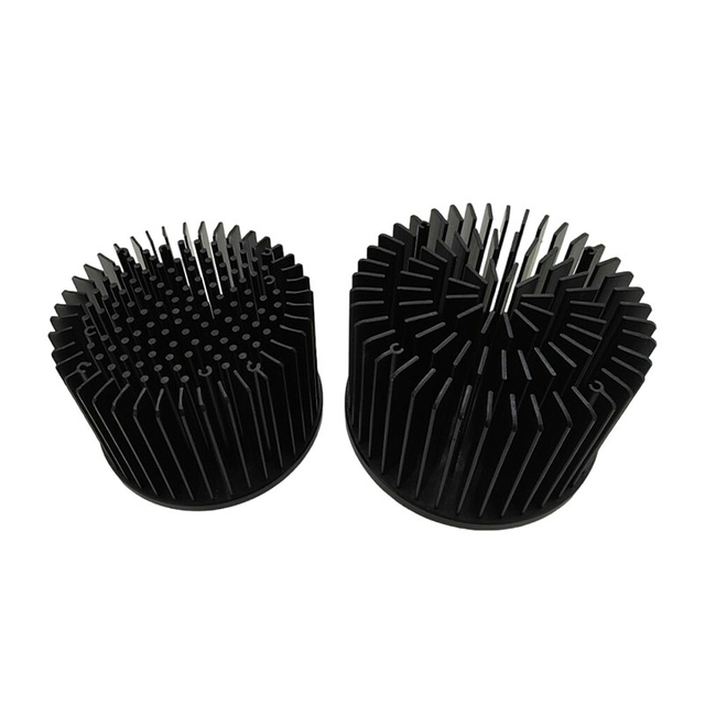
A billet is forged at room temperature in a die carrying the pin pattern; the metal flows up into the pin cavities and work hardens in place. The base is then machined flat and the outline trimmed to the drawing. Aluminum is the standard material; copper is forged on request where the spreading gain justifies the tool wear. How a pin field behaves against a fin stack is explained in pin fin heat sink explained.
Works whichever way the air crosses.
No cut per pin, no bond under the root.
Tolerant of a late fan choice.
Material follows the flux.
Fits the envelope you have.
| Base Material | Aluminum or copper, cold forged pin field |
|---|---|
| Pin Grid | Square pitch, forged |
| Material | Aluminum 1070 / 6063; copper C1100 on request |
| Base | Machined flat after forging |
| Outline | Trimmed to drawing |
| Base CNC Tolerance | Milling / drilling / tapping down to +/-0.005 mm |
| Dimensional Inspection | Hexagon CMM +/-0.001 mm; 2.5D optical projector |
| Quality System | ISO 9001:2015; IATF 16949:2016 |
| Capacity | 60,000+ thermal parts per year |
| Lead Time | Samples typically 7-15 days; production scheduled to volume |
Note: values above are KingKa build options and verified capability; final geometry, holes and finish are confirmed against your drawing.
Pin height and pitch come from the die, so a new pattern means a new tool. Where the requirement is close to an existing pattern, running that tool and machining the outline is much cheaper than a bespoke pin field.
Design & CFD. 3D layout with CFD review sizes the fin field, pipe route and base thickness to the load and airflow.
Base machining. Plate, pockets and pipe channels are milled on 50+ CNC centers to +/-0.005 mm.
Fin and pipe joining. Fins skived, stacked or extruded; pipes pressed and soldered; the stack joined to the base by the process the design calls for.
Face fly-cutting. Contact face machined flat after joining so the part sits true on the device.
Final inspection. Hexagon CMM (+/-0.001 mm) and 2.5D projector check critical features; 4-stage IQC / IPQC / FQC.
Fin pitch and height - measured against the drawing before packing.
Base flatness - fly-cut face checked on the contact side.
CMM report - critical dimensions to +/-0.001 mm.
Joint inspection - solder or weld fillet checked along the stack feet.
Visual and batch audit - IQC / IPQC / FQC on every run.
Pin fields are chosen where the airflow is uncertain:
Enclosed electronics boxes
LED drivers
Power supplies with unclear airflow
Telecom line cards
Industrial control modules
Send the base outline, the height, the pin pitch you need and the airflow you expect. KingKa matches the pattern to an existing die set where possible, then machines the base and outline to your drawing. The round version with a notched flange is the round pin fin heat sink.
KingKa is a direct manufacturer with 16+ years in thermal production, 50+ CNC centers, in-house skiving, FSW and vacuum brazing, certified to ISO 9001:2015 and IATF 16949:2016.
Ask for the closest existing pin pattern before quoting a new die - the difference in tooling cost is usually larger than the difference in thermal performance.
One supplier for the whole assembly. Base, fins, pipes and hardware under one quality system.
CFD before tooling. Design review catches a bad layout before metal is cut.
Prototype to volume. Samples in 7-15 days, production scheduled to forecast.